Dimpled blades for a vertical-axis wind turbine
Dr Mohammad Ghaffari · 2017 · Industry
Context
A vertical-axis wind turbine manufacturer wanted more power from its straight-bladed Darrieus rotor. Darrieus turbines are simple to build and work in any wind direction, but they are less efficient than horizontal-axis machines and weak at low speed. One proposed fix is to cut a small cavity, or dimple, into each blade. The project tested whether a dimple helps, and if so where it should sit, how big it should be and what shape it should have.
My role
I was the CFD engineer on the project, from model set-up through to the blade recommendation.
Approach
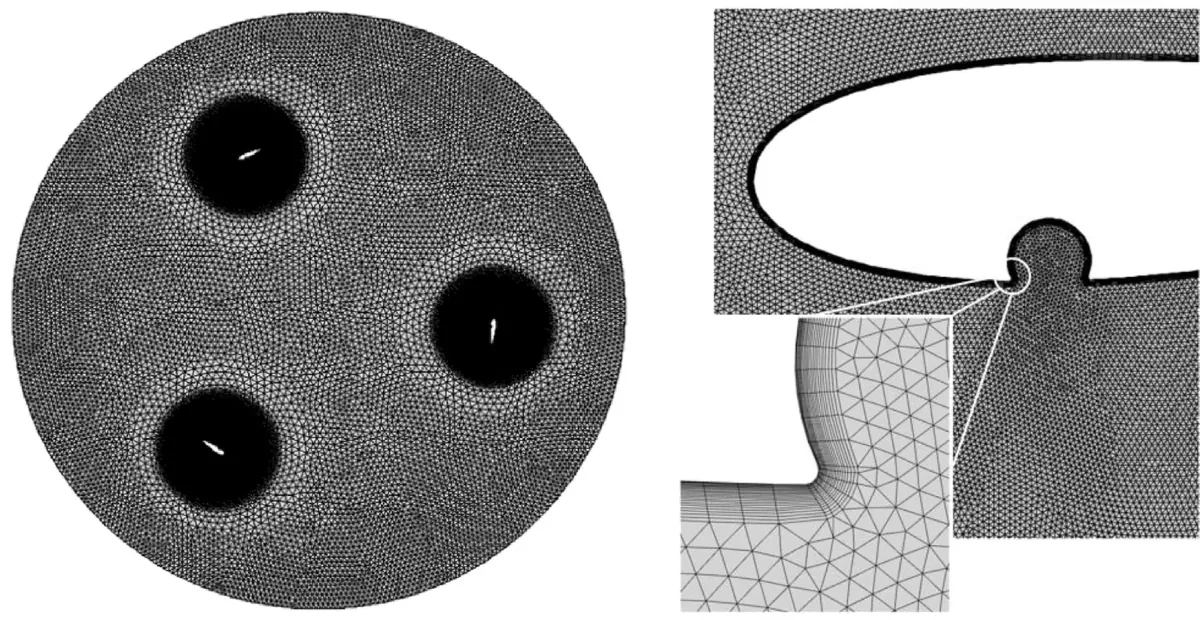
- Two-dimensional unsteady simulation of a three-bladed, straight-bladed rotor in OpenFOAM, with a sliding mesh for the rotating zone and the SST k-ω turbulence model.
- Rotor of 1.03 m diameter and 1.46 m height with NACA 0021 blades of 0.0858 m chord, at a wind speed of 9 m/s, matching a reference wind-tunnel test.
- Mesh-independence check on four grids. The third grid gave a power coefficient of 0.0143 against 0.0147 on the finest, and was used for all runs.
- Parameter sweep of the dimple: position (pressure or suction side, at a quarter, half or three quarters of the chord), diameter (2–8% of chord) and shape (circular, square or triangular).
Figures
Outcome
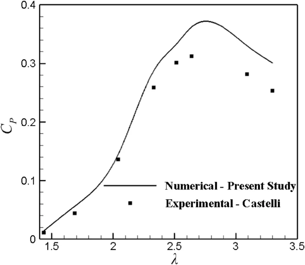
- The simulated power curve follows the wind-tunnel data of Castelli et al. (2011) up to a tip speed ratio of 2.6. Beyond that the blades stall, and the two-dimensional model over-predicts power.
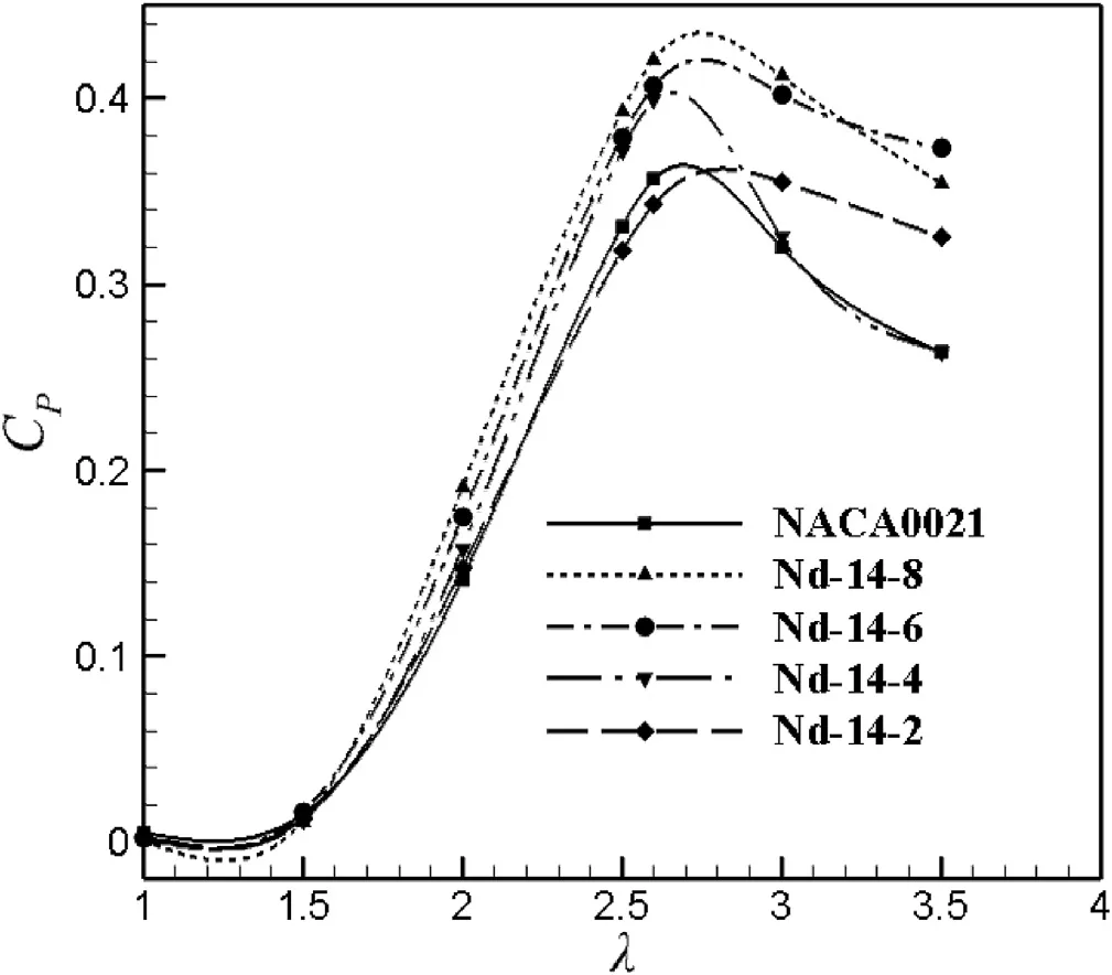
- The best blade had a circular dimple of 8% of chord on the pressure side, near the leading edge.
- With that blade, the power coefficient rose by 18% at the optimum tip speed ratio (λ = 2.6) and by 25% on average, against the plain NACA 0021 blade.
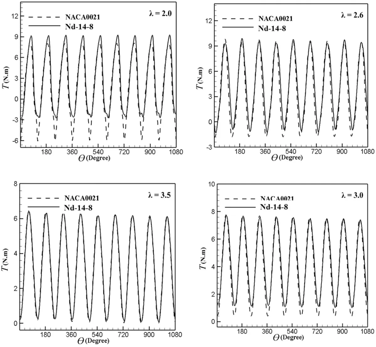
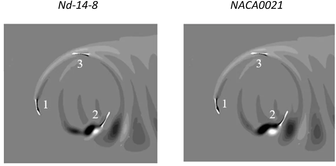
- Torque swings over each revolution were smaller, and the vortices shed from the dimpled blades were smaller and died out faster.
- Vertical-axis wind turbine
- OpenFOAM
- Sliding mesh
- SST k-ω
Commercial project. Details generalised.