Adjoint shape optimisation of a pitching aerofoil
Dr Mohammad Ghaffari · 2017 · Research
Context
Small aerodynamic devices such as micro air vehicles and small turbine blades run at low speed, where the flow separates and sheds vortices through every cycle. Most optimisation work assumes steady, high-Reynolds-number flow, which misses this behaviour. The aim here was to reshape an aerofoil pitching in turbulent, low-Reynolds-number flow for a higher time-averaged lift-to-drag ratio, using the continuous adjoint method so that each design step costs only one extra solve.
My role
I was the CFD engineer who set up the unsteady adjoint optimisation and ran the validation and design cases.
Approach
- Unsteady Reynolds-averaged Navier–Stokes solution with the Spalart–Allmaras turbulence model, on hybrid unstructured meshes.
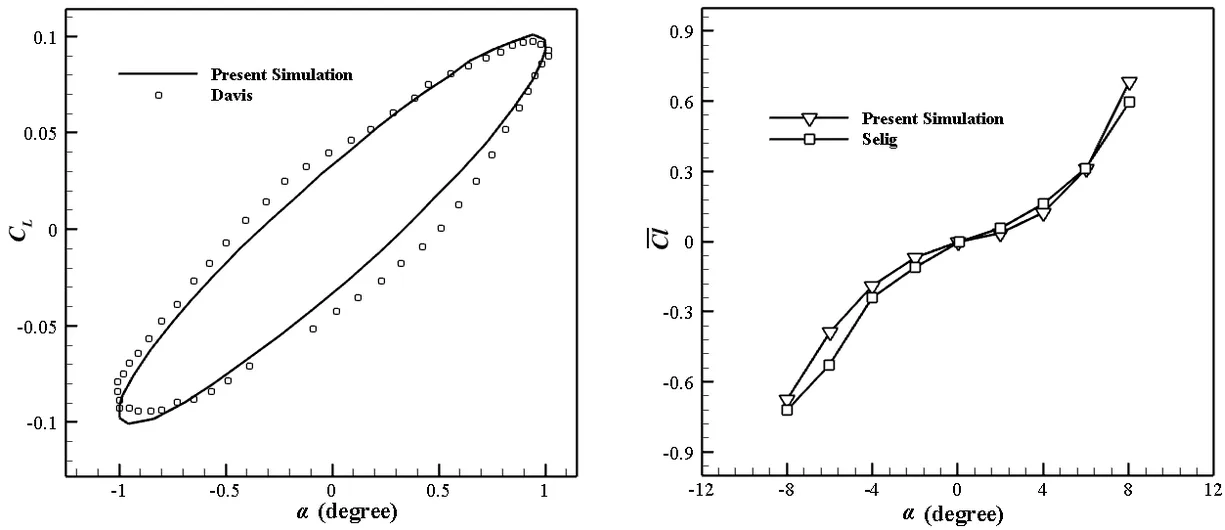
- Flow solver validated against two sets of experiments: a NACA 64A010 aerofoil pitching at Mach 0.796 (Davis), and static lift on the S809 aerofoil (Selig).
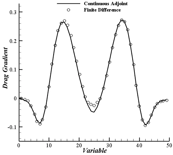
- Adjoint gradients checked against finite differences for all 50 free-form deformation design variables.
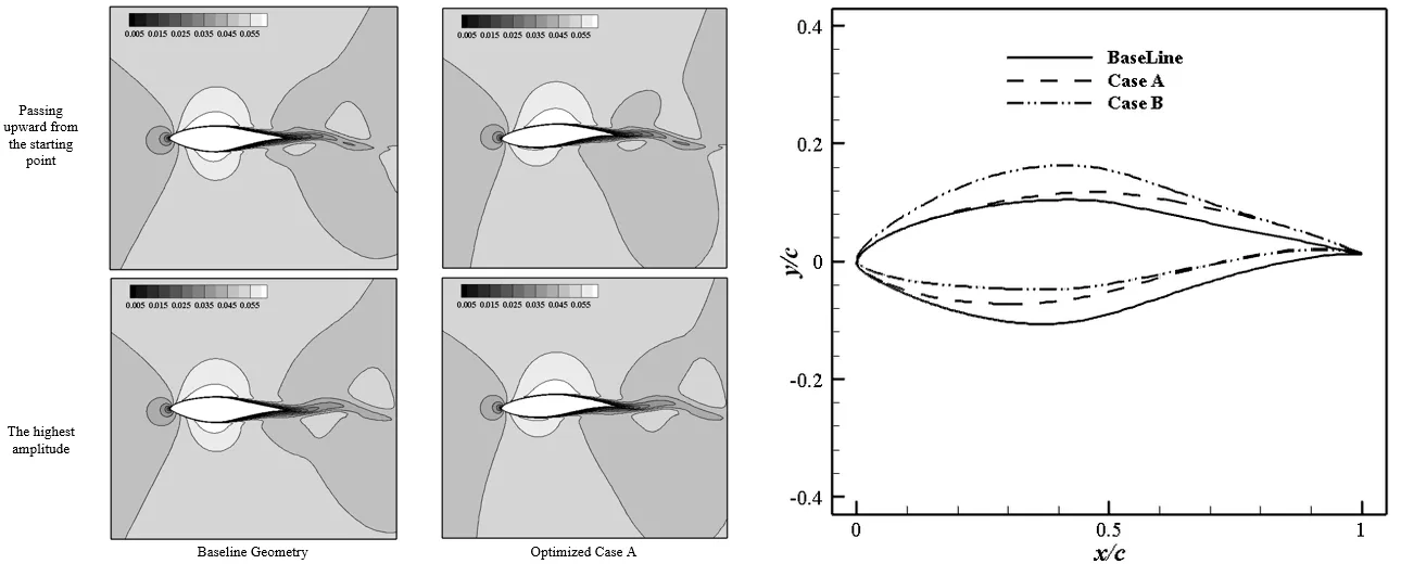
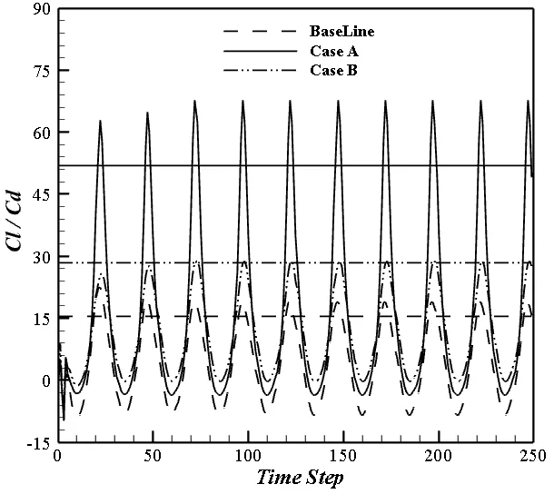
- S809 aerofoil pitching with an amplitude of 1.01° and a reduced frequency of 0.202, at Re = 50,000, on a 52,000-cell mesh. Two designs: case A without constraints, and case B with the baseline area and maximum thickness held.
Figures
Outcome
- The adjoint gradients match the finite-difference values across all 50 design variables.
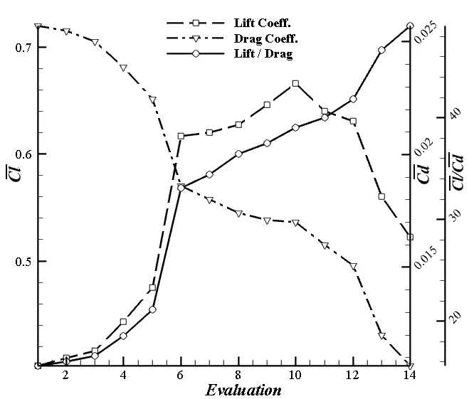
- Case A raised the time-averaged lift-to-drag ratio from 15.4 to 52, an increase of 238%, in 14 design cycles. Drag fell by 61%, but the aerofoil became thinner.
- Case B kept the baseline area and maximum thickness and still raised the lift-to-drag ratio to 28.4, an increase of 84%.
- Both designs reduced the curvature of the lower surface, which delayed separation and raised the average lift.
- Continuous adjoint
- Shape optimisation
- Unsteady RANS
- Free-form deformation
Later work: Turbulent adjoint optimisation framework